
Blog
Mitigating Shock and Vibration Damage in Global Transit: FDA & Medical CE Compliance for Aesthetic Laser Devices
2026年10月23日
Why Shock and Vibration Damage Is the Silent Killer of Aesthetic Laser ROI
Every year, aesthetic clinics and distributors worldwide receive laser systems that left the factory in perfect calibration—yet arrive with misaligned optical benches, cracked laser bars, and de-soldered diode arrays. The culprit is rarely visible on the shipping crate: cumulative shock and vibration exposure during air freight, ocean transit, and last-mile road delivery. For high-value devices incorporating 755nm Alexandrite, 808nm Diode, and 1064nm Nd:YAG modules, even a 15G non-operating shock event can shift the resonator cavity enough to degrade energy density (fluence) by 10–20% before the first patient is treated. This technical guide examines the engineering, packaging, and compliance protocols that protect clinical performance from factory to first fire.
The Physics of Transit Damage: What Actually Fails Inside a Laser Handpiece
Aesthetic laser systems are precision optical instruments dressed in rugged housings. Understanding failure modes requires separating shock (high-acceleration, short-duration transients) from vibration (sustained low-frequency oscillation).
Shock-Sensitive Components
- Laser bars and diode stacks: Imported laser bars are micro-soldered to copper heatsinks; peak shocks above 30G can crack solder joints, raising thermal resistance and accelerating emitter degradation.
- Optical bench alignment: Mirrors and lenses are mounted to sub-micron tolerances. A 20G shock can displace a dichroic mirror by 50–100 microns, altering spot size and beam homogeneity at the treatment plane.
- Sapphire contact cooling windows: Brittle sapphire can chip under edge-impact loads, compromising the epidermal cooling interface and creating a patient safety risk.
- Water-cooling circuits: Pump mounts and quick-disconnect fittings are prone to stress fractures, leading to coolant leaks and TEC overheating on first power-up.
Vibration-Sensitive Failure Modes
Sustained road vibration in the 5–200 Hz band is particularly destructive to fiber-optic delivery systems and connector ferrules. Resonant amplification can loosen SMA connectors, introducing fiber coupling losses that manifest as inconsistent pulse energy and unpredictable pulse widths in the 0.5–300ms range.
Critical Output Metrics: What Transit Damage Steals From Your Clinical Parameters
The table below maps the specification envelope of a typical multi-wavelength diode platform to the transit-induced degradation risk for each parameter. Use this matrix during incoming inspection and distributor acceptance testing.
| Key Parameter | Technical Specification | Transit Damage Risk |
|---|---|---|
| Wavelength / Laser Type | 755nm Alexandrite, 808nm Diode, 1064nm Nd:YAG | Misalignment shifts beam profile and wavelength stability |
| Energy Density (Fluence) | Up to 120 J/cm² (adjustable) | 10–20% fluence loss from optical bench displacement |
| Spot Size | 2–20mm adjustable | Beam homogeneity degradation from mirror shift |
| Pulse Width | 0.5–300ms | Inconsistent pulsing from fiber coupling loss |
| Cooling System | Sapphire contact cooling + TEC | Chipped sapphire window; coolant leak risk |
| Laser Bar Source | Imported laser bars, micro-soldered | Solder joint cracks above 30G peak shock |
| Compliance | Medical CE, FDA 510(k), ISO 13485 | CAPA and re-validation required after triggered shock indicators |
Engineering Countermeasures: Packaging, Isolation, and Verification
1. ISTA-Certified Packaging and Cushioning Design
Reputable OEMs design shipping containers to ISTA 3A and ASTM D4169 standards, targeting a drop height of 76–91 cm and random vibration profiles simulating LTL truck transport. Key design elements include:
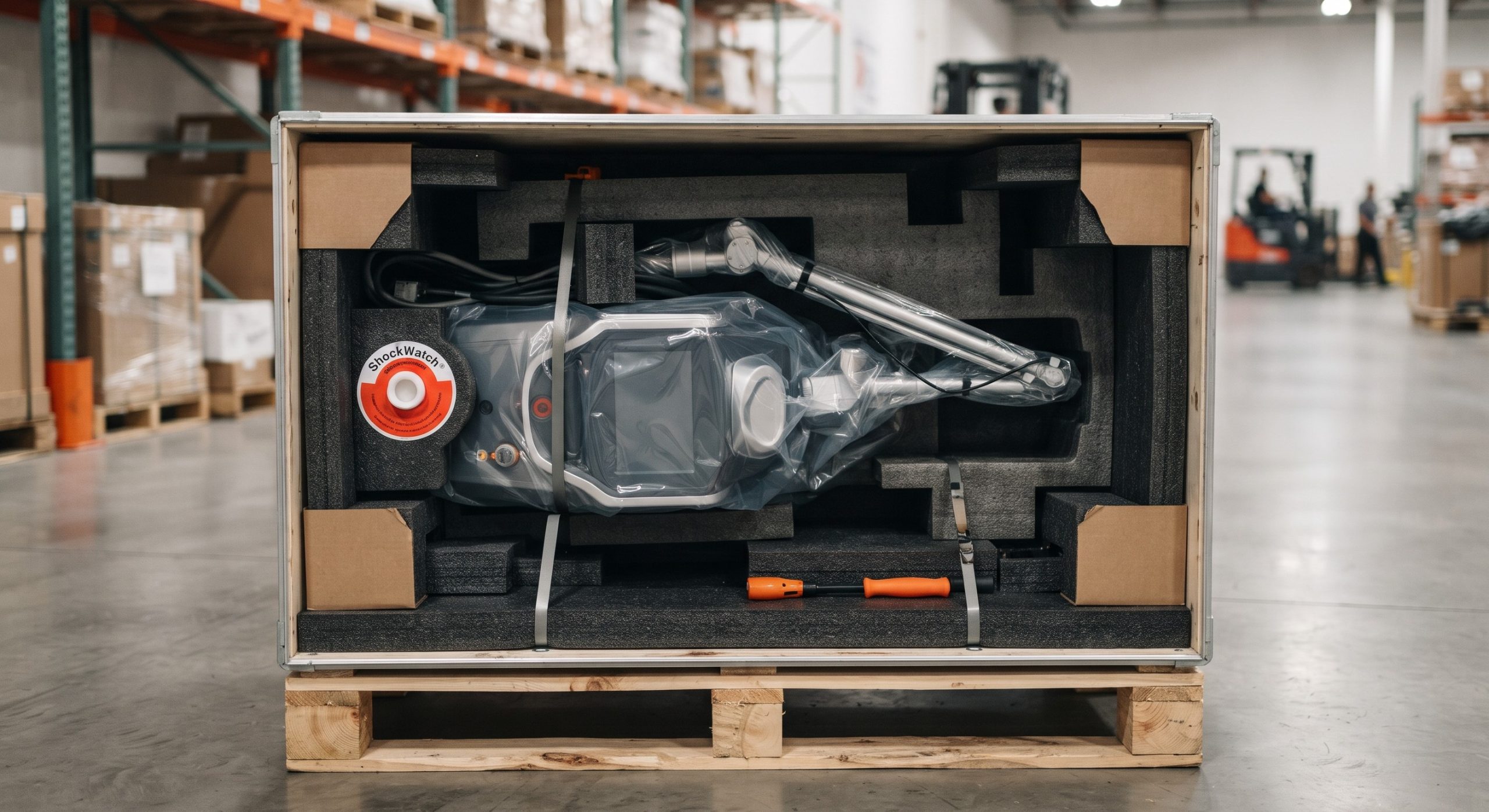
- Dual-density EPE foam cradles that decouple the optical head from the chassis.
- Shock-indicating labels (e.g., ShockWatch) and data loggers recording tri-axial G-forces throughout transit.
- Rigid inner crates for handpiece and fiber assemblies, which are the most shock-fragile sub-components.
2. Internal Shock Isolation
Best-in-class systems mount the optical bench on elastomeric isolators tuned to attenuate frequencies above 20 Hz. During transport, shipping locks (mechanical rigidizers) must be engaged and clearly labeled; clinics receiving devices should verify lock removal against the installation checklist—a step frequently missed in global deployments.
3. Incoming Inspection Protocol
Before signing the delivery receipt, perform a three-tier acceptance protocol:
- Tier 1 — Visual and data logger review: Check shock labels and download logger data; flag any event exceeding 25G peak.
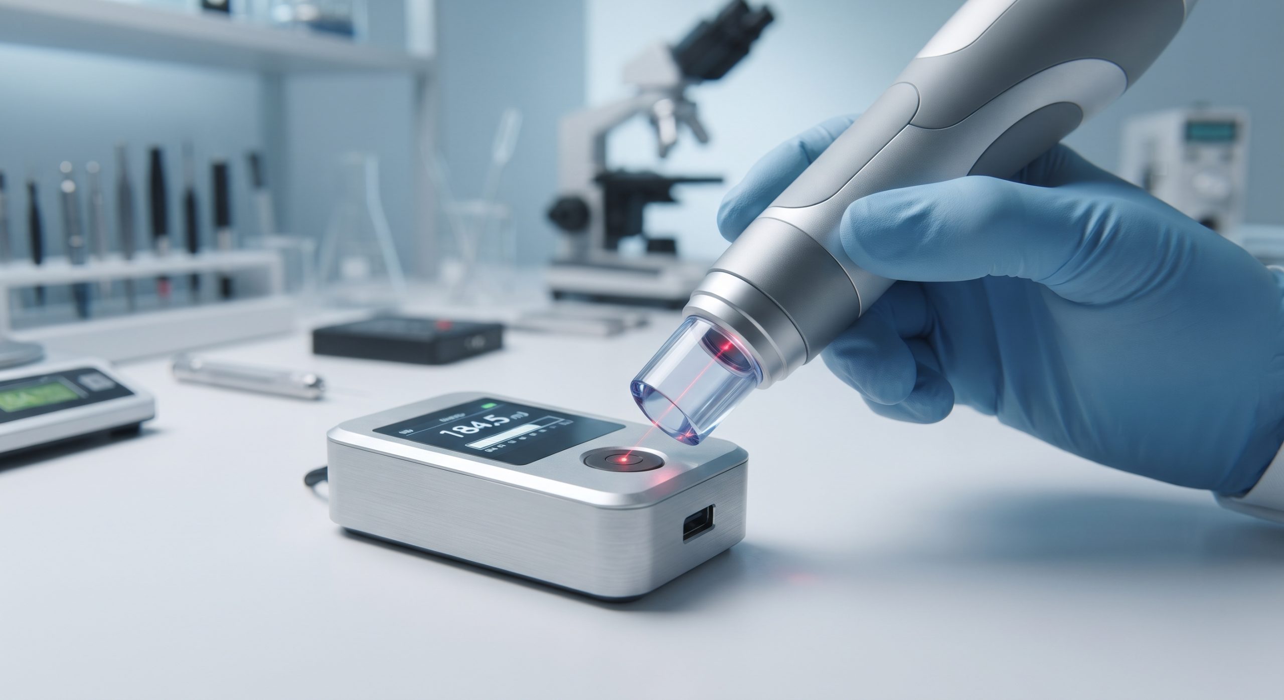
- Tier 2 — Power and energy verification: Measure fluence at the handpiece output with a calibrated energy meter across all wavelengths (755/808/1064nm); deviation above ±10% from factory calibration warrants service.
- Tier 3 — Cooling and thermal test: Verify sapphire window temperature reaches setpoint within specified time and confirm no coolant weep at fittings.
Regulatory Compliance: Aligning Transit Protection With Medical CE, FDA, and ISO 13485
Transit damage is not merely a commercial loss—it is a regulatory exposure. Under ISO 13485:2016, clause 7.5.11 (Preservation of Product) requires documented controls ensuring device conformity during handling and distribution. Medical CE (EU MDR 2017/745) mandates that packaging and transport conditions be validated as part of technical documentation, while FDA 510(k) cleared systems must demonstrate that shipping and storage conditions do not alter cleared indications or safety performance.
- Design validation: Retain ISTA/ASTM test reports and shock-logger datasets as part of the device master record.
- Distributor qualification: Audit freight forwarders against GDP (Good Distribution Practice) requirements, including temperature and shock monitoring for high-value capital equipment.
- Complaint handling: Any device received with shock indicators triggered must enter the CAPA process, with recalibration and re-validation documented before clinical release.
Clinics should request the OEM’s transit validation report and shock-indicator policy during procurement—a due-diligence step that protects both patient safety and the clinic’s insurance position.
Conclusion: Treat Logistics as a Clinical Parameter
Shock and vibration damage is predictable, measurable, and preventable. By demanding ISTA-certified packaging, verifying fluence and spot size at acceptance, and aligning distribution controls with ISO 13485 and Medical CE/FDA obligations, clinics and global distributors preserve the clinical efficacy and ROI of their 755nm/808nm/1064nm platforms from the first shipment to the thousandth treatment. In medical aesthetics, the supply chain is not a back-office function—it is the first line of clinical quality assurance.