
BLOG
Setting Up a Climate-Controlled Facility for Aerospace Parts: The Ultimate Engineering Guide to Environmental Control, Standards, and ROI
2026年11月3日
Why Climate Control Is the Hidden Backbone of Aerospace Parts Manufacturing
Aerospace components operate under extreme thermal, mechanical, and aerodynamic loads. A turbine blade that tolerates a 0.02 mm dimensional drift on the ground may fail catastrophically at altitude. This is why Setting Up a Climate-Controlled Facility for Aerospace Parts is not a facilities-management afterthought — it is a core manufacturing engineering discipline governed by AS9100D, ISO 9001:2015, and customer-specific special-process requirements such as NADCAP accreditation. Temperature swings induce differential thermal expansion between dissimilar alloys (e.g., Ti-6Al-4V versus Inconel 718), humidity drives corrosion and adhesive cure variability, and particulate contamination compromises bond integrity in composite structures.
In this guide, we break down the physics, the standards, the HVAC and metrology architecture, and the capital and operating economics of a compliant aerospace environmental control system — so engineering leaders can specify, validate, and justify the investment with confidence.
The Physics: Why Temperature, Humidity, and Particulates Drive Aerospace Non-Conformance
Thermal Expansion and Dimensional Metrology
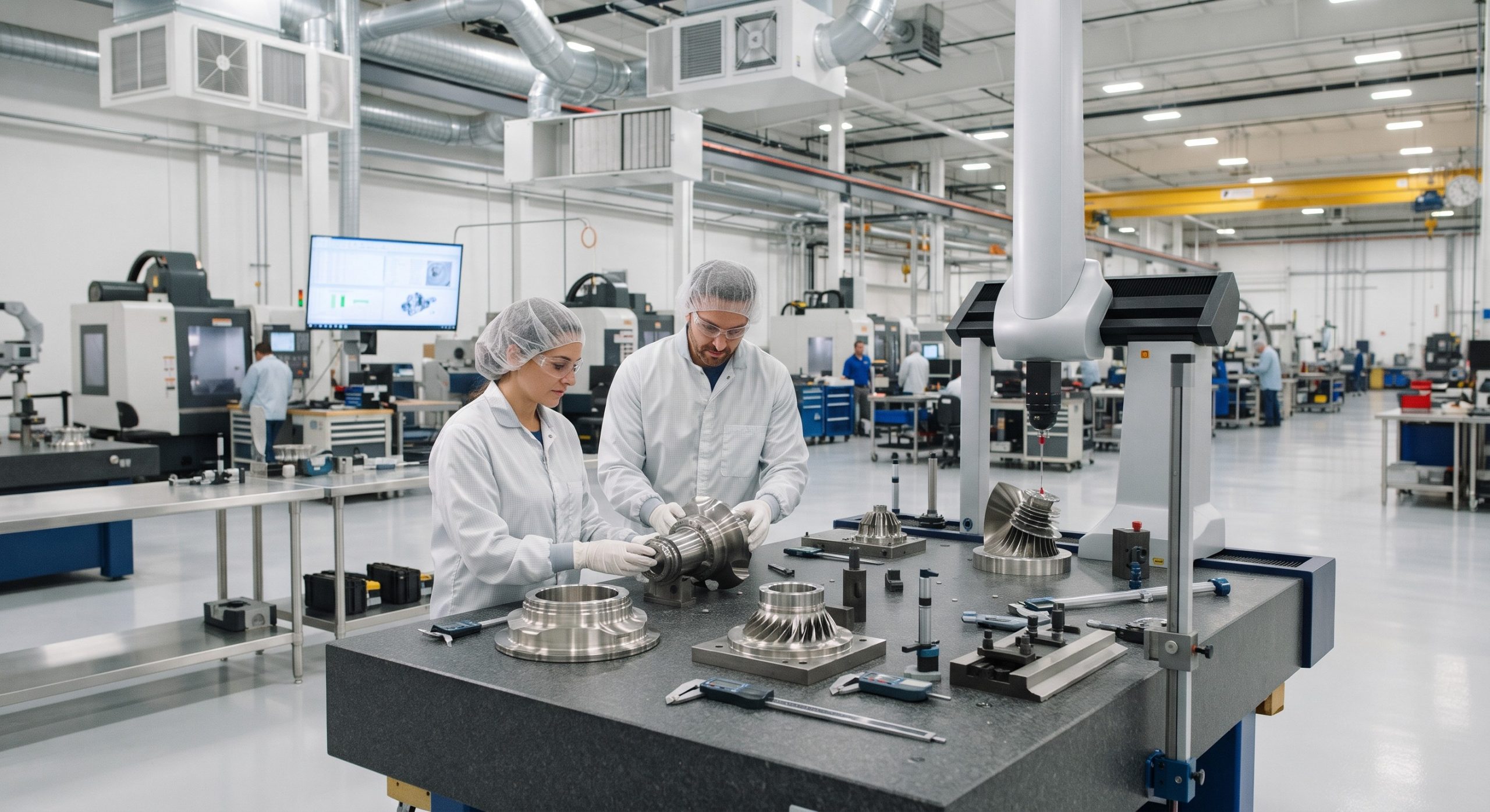
Most aerospace alloys exhibit a coefficient of thermal expansion (CTE) between 8.6 and 23.6 µm/m·K. For a 1,000 mm titanium structural spar, a ±5 °C deviation produces roughly ±45 µm of growth — enough to exceed typical GD&T tolerances on hole position and profile. CMM rooms and final inspection areas therefore require 20 °C ± 1 °C control per ISO 1:2022 and ISO 10360 acceptance testing, with gradients limited to <0.5 °C/m vertically.
Humidity and Corrosion/Adhesive Chemistry
Relative humidity above 55% RH accelerates galvanic corrosion on aluminum–steel fastening interfaces and degrades the shelf life of prepreg composites and structural adhesives. Conversely, RH below 30% promotes electrostatic discharge (ESD) risk in avionics assembly. Aerospace cleanrooms and bond rooms typically target 45% ± 5% RH with continuous dew-point monitoring.
Particulate and Outgassing Control
Composite layup and optical payload assembly demand ISO 14644-1 Class 7 (10,000) or Class 8 environments, with ISO 14644-2 monitoring schedules. Volatile outgassing from seals and lubricants must comply with ASTM E595 (TML < 1.0%, CVCM < 0.10%) to protect spacecraft optics and thermal control surfaces.
Regulatory and Quality Standards Framework
A credible climate-controlled facility is auditable. The compliance stack typically includes:
- AS9100D / ISO 9001:2015 — quality management system and control of monitoring equipment.
- NADCAP special-process accreditation for heat treating, bonding, and non-destructive testing environments.
- ISO 14644-1/-2 — cleanroom classification and monitoring.
- ISO 1:2022 — standard reference temperature for geometrical product specification.
- IEST-RP-CC006 — cleanroom commissioning and certification protocols.
- 21 CFR Part 11 / GAMP 5 — where electronic environmental records are used for traceability.
Architectural Design: Zoning, HVAC, and Redundancy
Zoning Strategy
Facilities should be segmented into metrology zones (20 °C ± 1 °C), composite bond rooms (22 °C ± 2 °C, 45% ± 5% RH), clean assembly areas (Class 7/8), and general machining zones. Each zone requires independent air-handling units (AHUs) with dedicated sensors and interlocks.
HVAC and Air Distribution
Typical design parameters: air change rates of 15–25 ACH for clean zones, HEPA H14 filtration at terminal points, and laminar flow over critical layup benches. Redundant chillers (N+1) and humidifiers prevent single-point failure. Pressure cascades of 10–15 Pa between zones prevent cross-contamination.
Monitoring and Data Integrity
Deploy calibrated RTD sensors (±0.1 °C) and capacitive RH sensors (±1.5% RH) with continuous data logging, alarm thresholds, and audit trails. Building management systems (BMS) should integrate with the QMS for automated non-conformance triggers.
Technical Specifications
The following matrix summarizes typical design parameters for a compliant aerospace environmental control system:
| Key Parameter | Technical Specification |
|---|---|
| Temperature Control (Metrology) | 20 °C ± 1 °C per ISO 1:2022 |
| Relative Humidity | 45% ± 5% RH (range 30–55%) |
| Cleanroom Classification | ISO 14644-1 Class 7 / Class 8 |
| Air Change Rate | 15–25 ACH with HEPA H14 filtration |
| Pressure Cascade | 10–15 Pa between adjacent zones |
| HVAC Redundancy | N+1 chillers and humidifiers |
| Monitoring Accuracy | RTD ±0.1 °C; RH sensor ±1.5% |
| Vibration Isolation | VC-C to VC-D for metrology zones |
| Outgassing Compliance | ASTM E595: TML < 1.0%, CVCM < 0.10% |
| Quality Standards | AS9100D, ISO 9001:2015, NADCAP |
Commissioning, Validation, and Ongoing Qualification
Commissioning follows IEST-RP-CC006 and includes empty-room and at-rest particle counts, airflow visualization, recovery testing, and temperature/humidity mapping at minimum 12 grid points per zone. Ongoing qualification uses continuous monitoring plus quarterly trend reviews, with annual revalidation against ISO 14644-2 limits. Metrology equipment must be calibrated under ISO/IEC 17025 accredited scopes, with traceability to national standards.
Treatment Areas & Facility Zones
Not all aerospace zones demand identical control. The following zone matrix aligns environmental requirements to production activities:
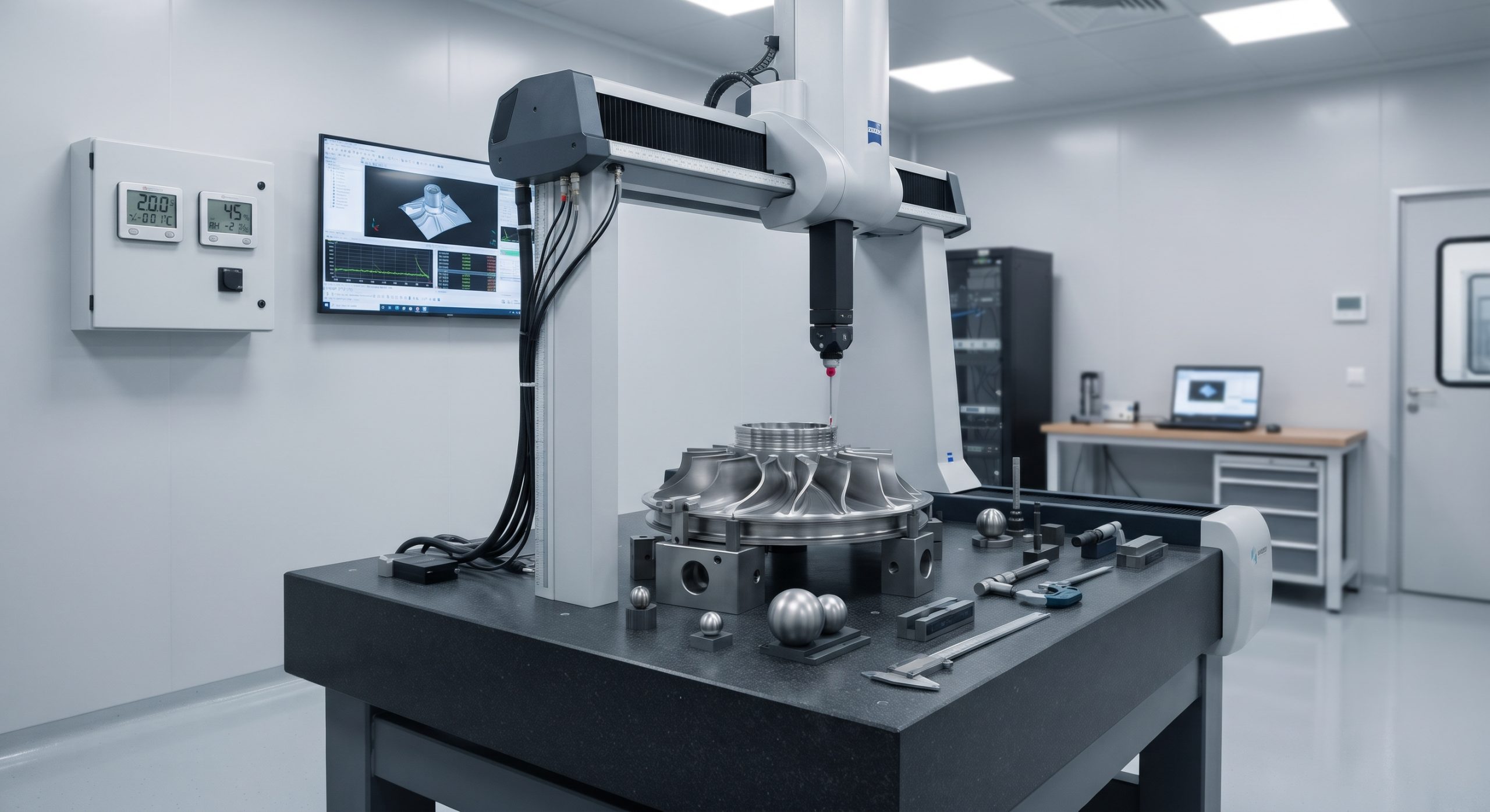
- Metrology / CMM Rooms: 20 °C ± 1 °C, 45% ± 5% RH, vibration isolation, Class 8.
- Composite Layup & Bond Rooms: 22 °C ± 2 °C, 45% ± 5% RH, Class 7.
- Avionics & ESD Assembly: 22 °C ± 2 °C, 40–50% RH, Class 8, ESD flooring.
- Surface Treatment & Paint: 23 °C ± 2 °C, 50% ± 5% RH, dedicated exhaust with VOC control.
- Final Assembly & Test: 22 °C ± 3 °C, 50% ± 10% RH, Class 8.
ROI, Operating Economics, and Executive Verdict
Capital and Operating Cost Drivers
CapEx for a 2,000 m² aerospace facility typically ranges from USD 2.5–5.0 million for HVAC, cleanroom envelopes, and monitoring, depending on cleanroom class and redundancy. OpEx is dominated by energy: HVAC systems consume 40–60% of facility electricity, with heat recovery, variable frequency drives, and enthalpy-based economizers delivering 15–25% energy savings.
Quantified Business Case
Industry data consistently show that environmental excursions are among the leading causes of rework and scrap in precision aerospace manufacturing. A single out-of-tolerance metrology escape can trigger USD 50,000–500,000 in containment, customer notification, and root-cause investigation costs. A validated climate-controlled facility typically pays back within 18–36 months through reduced non-conformance, improved first-pass yield, and audit-ready compliance — while also unlocking higher-tier customer approvals (e.g., Tier 1 OEM special-process listings).
Executive Verdict
Setting up a climate-controlled facility for aerospace parts is best approached as a risk-managed capital program, not a utility upgrade. Specify zones against ISO 1:2022 and ISO 14644 limits, validate to IEST-RP-CC006, integrate monitoring into your AS9100D QMS, and build N+1 redundancy into critical HVAC and humidity systems. Organizations that treat environmental control as a first-class engineering requirement consistently achieve lower cost of poor quality, faster customer qualification cycles, and a durable competitive moat in the precision aerospace supply chain.